JBR MILLING GUIDELINES FOR OPTICAL MIRRORS AND LENSES
1、 Introduction:
This specification should be applied for the machining of all punches which are destined to inject parts with an exclusive optical function such as :
punches for lighting mirrors with following surfaces : Parabolas, SC1, SC1+, SC2, SC3, SC3X, elliptic…etc , and also for the punches to inject plastic lenses.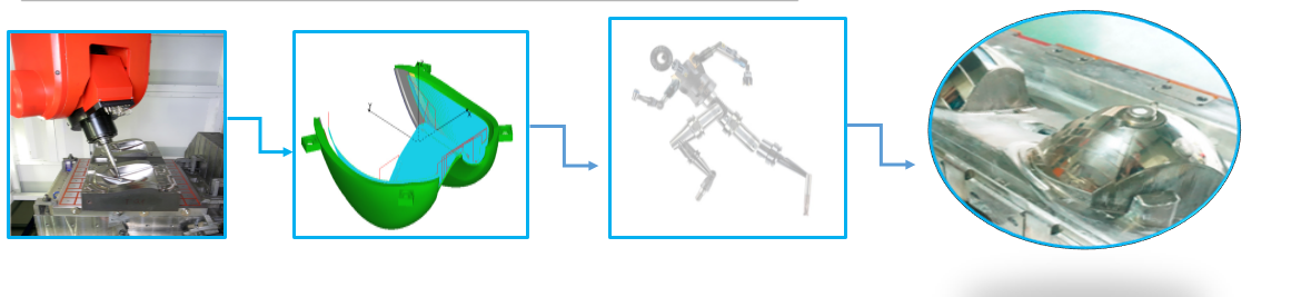
2、Recommendations concerning “Machining Techniques and Strategies”
High speed milling (>15000 revolutions/minute) is recommended for the machining of the punches for optical parts, this in respect to the usual curves and in function of the machining times generated by the complexity of the optical .
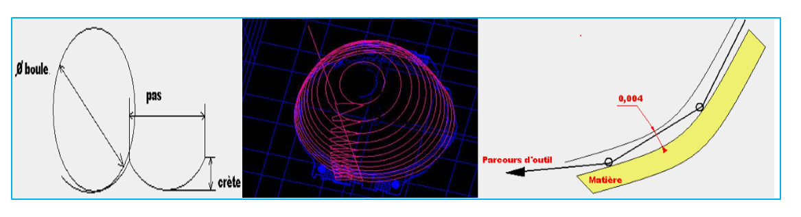
For the final milling the CAM program CATIA V5 , which gives the best results in respect to the surface finishing and in respect to the surface shape, is highly recommended. During the final milling the diameter of the tool and the step will be calculated in function of
the topology of the applied surface. In any case the step should not generate a ridge between to steps, which overruns 0,005 mm perpendicular to the surface shape.
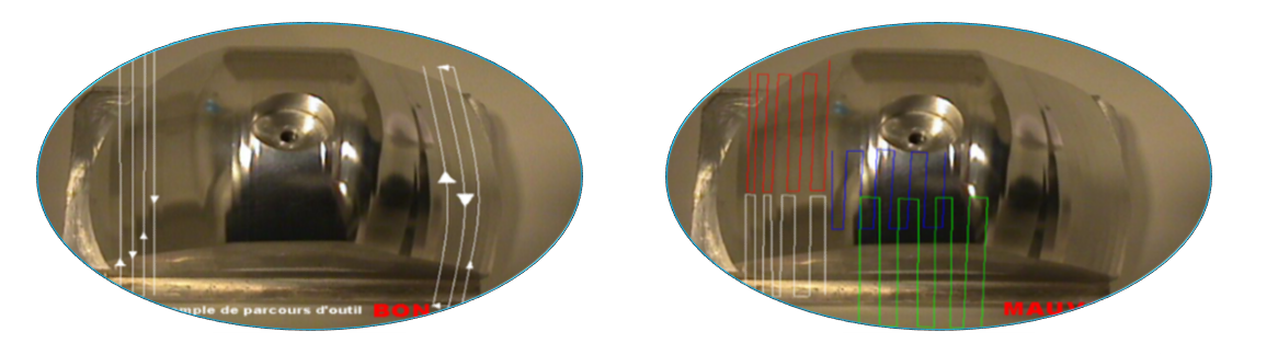
3、 Requirements concerning machining and tool cutting path:

4、 In the case of plastic lenses:
5/Control for optical punches:
All mechanical l part with an optical function must have a 3D surface control and will be followed by a quality sanction following operating instructions in the blue text here under
The basic requirement is:
The standard deviation for the global optical surface should not exceed +/-0.005mm.
The local maximum allowed deviation should not exceed +/-0.02 mm
These figures could eventually be modified in function of the requirements resulting from the optical study (e.g. the punches for elliptic modules could generate specific restraints inducing a more restricted tolerance gap). The final interpretation is the responsibility of the Valero optical Laboratory.
SUMMARY:After measuring of the surface of the punch the unit of points are to be repositioned by “PROSE” or equivalent. Display of the results is done by “is deviations”, or by “local cuts” as shown in the example here under.